Support and Reinforcement in the Mining Cycle

The most commonly used mesh is probably welded mesh made of approximately 5 mm thick steel wire and having 100 mm square openings. The steel wire may be galvanised or not. The alternative has been an interwoven mesh known as chain link mesh. The disadvantage of traditional chain link mesh compared with weld mesh has been the difficulty of applying shotcrete successfully through the smaller openings available. This difficulty has now been overcome in a high strength, light weight chain link mesh with 100 mm openings which is easy to handle and can be made to conform to uneven rock surfaces more readily than weld mesh.

A feature of this mesh is the fact that the intersections of the wires making up the squares in the mesh are twisted rather than simply linked or welded. Roth et al. (2004) describe static and dynamic tests on this mesh. Mesh of this type is being used successfully at the Neves Corvo Mine, Portugal, where it has been particularly successful in rehabilitating damaged excavations. Li et al. (2004) report that this mesh is being trialled by St Ives Gold, Western Australia. Tyler & Werner (2004) refer to recent trials in sublevel cross-cuts at the Perseverence Mine, Western Australia, using what a similar Australian made high strength chain link mesh. It is understood that completely satisfactory mechanised installation methods have yet to be developed.

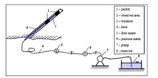
In this symposium, Hadjigeorgiou et al. (2004) and Van Heerden (2004) discuss the use of cementitious liners to support, protect and improve the operational performance of ore passes in metalliferous mines. One of the benefits of cementitious liners is the corrosion protection that they provide to the reinforcing elements. Both papers emphasise the need to consider the support and reinforcement of ore passes on a cost-effectiveness basis taking into account the need to rehabilitate or replace failed passes. The author has had the experience of having to recommend the filling with concrete and re-boring of critical ore passes that had collapsed over parts of their lengths.
Although their use was referred to at the 1999 symposium, there have been significant developments in the use of thin, non-cementitous, spray-on liners (TSLs) since that time (e.g. Spearing & Hague 2003). These polymer-based products are applied in layers of typically 6 mm or less in thickness, largely as a replacement for mesh or shotcrete. Stacey & Yu (2004) explore the rock support mechanisms provided by sprayed liners.
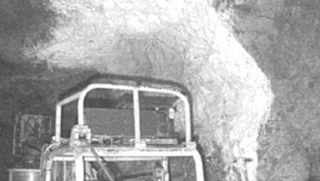
The author’s experience at the Neves Corvo Mine, Portugal, is that TSLs are useful in providing immediate support to prevent rock mass deterioration and unravelling in special circumstances (Figure 2), but that they do not yet provide a cost-effective replacement for shotcrete in most mainstream support applications. In some circumstances, they can be applied more quickly than shotcrete and may be used to provide effective immediate support when a fast rate of advance is required. Recently, Archibald & Katsabanis (2004) have reported the effectiveness of TSLs under simulated rockburst conditions.
Overcoming the limitations and costs associated with the cyclic nature of underground metalliferous mining operations has long been one of the dreams of miners. More closely continuous mining can be achieved in civil engineering tunnelling and in longwall coal mining than in underground hard rock mining. Current development of more continuous underground metalliferous mining systems is associated mainly, but not only, with caving and other mass mining methods (Brown 2004, Paraszczak & Planeta 2004).
Several papers to this symposium describe developments that, while not obviating the need for cyclic drill-blast-scale-support-load operations, will improve the ability to scale and provide immediate support and reinforcement to the newly blasted rock. Jenkins et al. (2004) describe mine-wide trials with hydro-scaling and in-cycle shotcreting to replace conventional jumbo scaling, meshing and bolting at Agnew Gold Mining Company’s Waroonga mine, Western Australia. Neindorf (2004) also refers to the possibility of combining hydro-scaling with shotcreting to develop a new approach to continuous ground support in the development cycle at Mount Isa. These developments form part of the continuous improvement evident in support and reinforcement practice in underground mining.
As was noted at the 1999 symposium, although backfill has been used to control displacements around and above underground mining excavations for more than 100 years, the great impetus for the development of fill technology came with the emergence of the “cut-and-fill era” in the 1950s and 60s (Brown 1999a). It was also noted that fill did not figure prominently in the papers presented to that symposium. A few years earlier, paste fill made from mill tailings and cement and/or other binders, had been developed in Canada (Landriault 2001). Since that time, the use and understanding of paste fill have increased dramatically, so much so that Belem et al. (2004b) suggest that it is “becoming standard practice in the mining industry throughut the world”.
Cemented paste fill is now used with a range of mining methods including sublevel open stoping, cut-and-fill and bench-and-fill. In some applications, it is necessary that unsupported vertical paste fill walls of primary stopes remain stable while secondary stoping is completed. In common with Landriault (2001) and Belem et al. (2004a), the author has had success using the design method proposed by Mitchell (1983). A particular requirement in some applications is to include enough cement to prevent liquefaction of the paste after placement (Been et al. 2002).
In two papers to this symposium, Belem et al. (2004a, b) discuss a range of fundamental and applied aspects of the use of cemented paste fill in cut-and-fill mining generally, and in longhole open stoping at La Mine Doyen, Canada. Varden & Henderson (2004) discuss the use of the more traditional cemented rock fill to fill old underground mining voids at the Sons of Gwalia Mine, Western Australia.

Underlying strata failure due to mining

Coal extraction causes strata deformation and failure which may enhance hydraulic conductivity in the surrounding strata. Therefore, it is desirable to accurately determine pre- and post-mining hydraulic conductivities in the overburden and underlying strata of the coal seam. To measure the hydraulic conductivity in the underlying strata, boreholes are drilled pre-mining in underground roadways for observation. In each borehole, water injection and a number of well logging techniques (such as electric resistivity, sonic log, acoustic emission, and hole televiewer, etc.) are used to determine rock strength, borehole fissure, and changes in hydraulic conductivity.
Figure 10.1 gives a schematic diagram of a water injection instrument (Zhang and Zhu 1994). The key technique during measurements is to control the injection pressure. The pressure should not be high enough to create new fractures in the strata, since the experiment is to determine the changes in hydraulic conductivity induced by mining. Therefore, the injection pressure should not exceed the least principal stress of the surrounding strata. Figure 10.2 shows the observing borehole locations and layout in Xingtai coal mine. In-situ stresses in this area were: V v = 7.4 MPa, V h = 4.5 MPa. The roadway in Fig. 10.2 was located 36 m below the mining face and four boreholes were drilled at different angles. The water injection instrument described in Fig. 10.1 was applied to measure the flowrate of water injection pre- and post-mining, using an injection pressure of 0.35 – 0.5 MPa. The water injection along each borehole was conducted by pumping water into the instrument, then into the borehole. The measurements were taken in each hole at different sections throughout the borehole and at different times.

Figure 10.3 presents the measured pre-mining and post-mining flowrate of water injection in Hole 1 (refer to Fig. 10.2). Note that in this context pre-mining corresponds to a state before the mining face passes the borehole, and post-mining means after the mining face passes the borehole. Before the mining face passed Hole 1 (in pre-mining the mining face was 32 m away from the borehole), the injection rate was zero from 53 to 68 m in the inclined borehole. This means that the strata in this area were impermeable. However, when the mining face passed the borehole, the injection rate (refer to Fig. 10.3 for post-mining at 19 and 63 m) increased dramatically, and the strata in some areas changed from being impermeable to permeable. Since the borehole wall collapsed by mining when the mining face passed 63 m from the borehole, water injection data could not be obtained after 60 m from the borehole opening. The borehole collapse in post-mining illustrates that the borehole was seriously damaged, and that rocks around the borehole failed due to mining.

Figure 10.4 plots the increments of water injection rates after mining, which were obtained by subtracting the pre-mining injection rates from those of the post-mining (Zhang 2005). These increments represent injection rates caused by permeability changes induced by coal extraction. Figure 10.4 shows that along the inclined borehole from 43 m to 72 m (the borehole end), the injection rate increases compared to the pre-mining (insitu) state. Therefore, the strata in this area were fissured by mining, and this fractured area is defined as the water-conducting failure zone. Using the same method to analyze the observed data from all boreholes, the mining-induced water-conducting failure zone can be obtained. This failure zone is of critical importance for mine design and water inrush prevention for mining over aquifers. Figure 10.5 shows the changes of the average water injection rate in the seam floor of 10 m deep from the seam in the Xingtai coal mine. The injection rate clearly increases compared to the unmined area. The injection rate decreases inside the abutment. This decrease is due to stress concentration and high abutment pressure occurring in this area, causing the fractures to close.
Figure 10.6 displays the changes of the injection rates with distance of mining advance for two different depths beneath the coal seam in Wangfeng coal mine, Hebei Province. It clearly shows that in the mined area the injection rate increases significantly compared to the unmined area. It also can be seen that due to coal extraction the water-conducting capacity increases in the floor strata, and this water-conducting capacity decreases as the distance from coal seam to the floor strata increases. This indicates that the closer the strata is to the extracted seam, the higher the permeability in the seam floor. It is also noticeable that the injection rate decreases inside the abutment. This decrease is due to the fact that stress concentration and high abutment pressure occurred in this area cause the fractures to be closed.
Field observations have shown that characteristics of failures in the floor strata are considerably different for different inclinations of the extracted seams. For flat or slightly inclined seams (dip angle, D < 25q), the profile of the water-conducting failure zone is broad in section with extended lobes, and the maximum failure depth occurs beneath the headgate and tailgate, respectively shown in Fig. 10.7 (Fengfeng Mining Bureau et al. 1985). For inclined seams (25q < D < 60q), the failure zone propagates downwards in an asymmetric manner in the dip direction, as shown in Fig. 10.8 (Huainan Mining Bureau et al. 1983). The extent of the failure zone increases gradually from updip to downdip, and the maximum failure depth appears in the floor strata beneath the area around the lower gate. For steeply inclined seams (60q < D < 90q), the failure zones in the floor strata are opposite to the inclined seams, i.e., the maximum failure depth appears in the strata beneath the area around the upper gate (Zhang 2005).

Immersion of Metals and Alloys

It is the differential electrical potential between the anode (+) and the cathode (-) which is key to the moist corrosion example described above. This differential is primarily generated by the difference in oxygen availability between the edge and the centre of the water droplet.

Differential potentials can also be generated by the presence (and contact) of dissimilar metals immersed in an oxygenated electrolyte solution (Illston et al., 1979; Bryson, 1987). Corrosion induced by such a coupling can be extremely aggressive and can result from the designed use of dissimilar metals (steel cables with aluminum plates or anchors) or from the presence of cablebolts in a rich sulphide ore. Indeed, rock bolts in sulphide ore bodies have significantly reduced service lives (Hoey and Dingley, 1971; Gunasekera, 1992).
Corrosion cells can also be generated on cablebolt surfaces at the point where abrupt transitions in environment occur. These include differential grout coverage, for example, at the borehole collar, at penetrating cracks in the grout, where the cable crosses a local water table, or within voids in the grout column. Oxygen (atmospheric or dissolved) is the critical component of the cathodic reaction discussed so far.
The concentration of oxygen is therefore a critical factor governing the rate of corrosion. In aqueous environments with high levels of acidity or low pH, however, the hydrogen (H ) ions in the acid solution react +cathodically with the free electrons in the steel to form hydrogen gas (H ). This 2 reaction is countered as before by the release of iron ions from the steel and does not require the presence of oxygen. While oxygen concentration normally controls corrosion rate (loss of iron ions), the acid (H ) reaction dominates below a pH of +4 and can become extremely aggressive.
Although it is not as common as oxygen related corrosion, acid corrosion can pose a serious hazard to mine support (Gunasekera, 1992) due to its accelerated rate. Sampling of groundwater and/or mine water for pH is relatively simple so the risk can be easily determined. In Canada, mine water with a pH of 2.8 has been recorded in underground mines, and measurements of 3-4 are not uncommon (Minick and Olson, 1987). Acidic mine water can often be linked to the oxidation of sulphide ores (primarily pyrite and marcasite) resulting in the generation of sulphuric acid and pH levels as low as 1.5-2 (Gunasekera, 1992).
In addition, there are many species of bacteria which flourish in the underground environment and which greatly accelerate the breakdown of sulphides to form sulphuric acid. Different species are active with and without the presence of oxygen. Such bacteria can accelerate the production of acid in mine waters by a factor of four with a related increase in corrosion rate.

Accelerated Corrosion

Of primary consideration in cablebolting is the acceleration of any of these corrosion processes at points of excessive strain in the cablebolt. As steel is strained in tension or in shear across a joint in the rock by rockmass movement, or bent by improper plate installation, the susceptibility to all forms of corrosion increases. Any protective surface rust is cracked by such strain exposing fresh surfaces. Microscopic cracks formed in areas of high strain create corrosion conduits beyond the steel surface. In addition, the strained ionic bonding in the metal increases the potential for iron-electrolyte interaction and hydrogen embrittlement (Littlejohn and Bruce, 1975).
This so-called stress corrosion cracking is important because cables will tend to corrode much more rapidly in aggressive environments exactly when and where their mechanical integrity is most tested and is most critical. In the case of grouted cablebolts, load concentrations along the cable length are usually related to full cracking and separation across the grout column. This allows direct and focussed attack on the stressed steel by corrosive agents. Stress corrosion is often the final mechanism in cablebolt failure in corrosive environments.

Cablebolt Geometry Effects

In general, the high carbon steels used in the manufacture of cablebolt strand are more corrosion resistant than the steels used in conventional rock bolts. Nevertheless, certain features of the grouted cablebolt which increase its potential for detrimental corrosion include the presence of flutes (v-grooves), internal channels between the outer wires and the king wires, as well as the formation of concentrated corrosion sites at separation planes in the rock and grout. Voids and bubbles in the grout column also create potential corrosion cells.

Summary Recommendations for Corrosive Environments

Corrosion is rarely a problem in open stope cable support, simply due to the short service life involved. Cut and fill stopes can be open for up to a year or more and overhead cables should, therefore, not be allowed to corrode to unacceptable levels during this time. Fractured, sulphide ore bodies require special attention in this regard. Corrosion of cablebolts (and other steel support) in permanent mine openings can cause serious problems in terms of safety and rehabilitation. In addition to normal capacity reduction, corroded cables tend to become brittle and can suffer reduced effectiveness in dynamic loading situations. The factors which contribute to corrosion are often complex, are compounded in an underground environment, and are very difficult to combat in areas of high severity. Nevertheless, the following is a brief list of remedial measures for use when corrosion has been identified as a problem (Littlejohn, 1990; Gunasekera, 1992).

Cablebolt storage

– Store cablebolts in a dry location, preferably moving them underground to the working site only when required. Long-term storage outside, under the sun or exposed to the elements should also be avoided.
– Do not allow water to collect on the cablebolts. Corrosion will quickly fill the flutes reducing bond strength and potentially pitting the steel.

Installed cablebolts

– High humidity accelerates corrosion. Good ventilation at all times can help to reduce this factor.
– Use caution when installing cables in areas with flowing water.
– Avoid any use of cements, mixing water or admixtures containing chlorides, sulphides or sulphites.
– Grout voids and bubbles increase corrosion potential.
– Request that plates, barrels and wedges, and other fixtures are electro-chemically compatible with the high strength carbon steel used in strand.
– Long rust stalactites growing rapidly from the ends of uphole cables indicates potentially severe strand corrosion up the hole.
– Sulphate resistant grouts are alkaline and can counteract acidic mine waters. The use of this cement does not permit the use of such waters for grout mixing.

Severe corrosion

– Epoxy-encapsulated cables are available for use in corrosive environments (Windsor, 1992). Note that such coatings may not be resistant to all forms of corrosion and that the coating must penetrate the strand, encapsulating the king-wire to prevent focussed corrosion down the centre of the strand.
– Galvanized cable would be of use against non-acidic corrosion.
– Grease can protect ungrouted lengths of cable (at the collar, for example).
Other more costly measures such as cathodic protection are discussed in Littlejohn and Bruce (1975) and Littlejohn (1990; 1993).